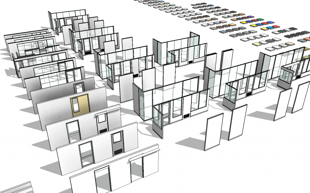
Ever wanted some internal glazing and partitioning systems for Revit? That’s what I’ve been working on lately for another manufacturer who sees the value of BIM and supplying high quality Revit content for their customers.
This one had me tossing up between the best approach to create them. Should I use curtain walls or not? Ultimately I chose NOT. Why?
- Curtain Panels aren’t particularly nice for scheduling. We want to schedule the size including the frame.
- The way in which a curtain panel meets a mullion isn’t configurable enough, in this case we needed panels to overlap mullions.
- We could have avoided mullions and built in the frame into the panel, but as most of these systems integrate with steel and timber stud partitions this seemed like it was just making extra work for the end user with the only benefit being the ability to quickly place a number of windows very quickly.
So with that I created them all as wall hosted Windows/Doors:
Each System has numerous options that are controlled with simply Yes/No checkboxes. Validation is done in the back end to ensure there are no illegal combinations. These include Options for:
- Shadowlines
- Full Height
- Head/Sill
- Materials
- Left/Right Joiners (for when you have 1 window hard up against another)
- Corner Options
- Number of Panels (for butt glass panels)
- All ANZRS Door Parameter controls for Size (all formula driven so you only set the panel size)
- Doors have additional options for:
- Timber or Aluminium Panels
- Grilles (including size options)
- Vision Panels (including size options)
- Mid Rails (including size options)
- Wide Stiles
- Guide and Track Options
- Flush/Pelmet Head Options
- Side or Top Fixing
- Wall Types have:
- Built in Skirtings
- Built in Reveals for Shadowlines
- Built in Ceiling Channels
Of course all the parameter fields have been populated, materials have been created for the 200 colours options available for Anodising and Powdercoating.
There are also a series of Face and Cavity sliders. These are designed to suit partitions of particular sizes. EG: A stud of 90/92mm with a single layer of 10/13mm plasterboard either side. As such I’ve built in validation into the door so it detects the finish and core thicknesses, if it isn’t with the tolerance a warning message is displayed in plan. This required some trickery as if you don’t do it a certain way the door would break when there was no finish to one side. Technically that’s correct, but the end user may assume the door is broken, so instead I allowed it to be placed and just provided the warning message.
Of course in Plan/Elevation we have appropriate Coarse/Medium/Fine detail so the documentation is clear and readable. With consistent symbology. At Coarse level we only see simply box sections for frames and single lines for the panes.
I’ve done my best to keep file size to a minimum, but given the number of options available there were some limitations to how small I could keep things. Considering a single door can do so much it probably does what it would take 10 normal doors to do. If the average door is 450KB, that equates to 4.2MB. These Doors range from 400KB to 1.1MB maximum I’d say that’s a reasonable achievement.
Finally type catalogs have been created with all the most common sizes and configurations so you can easily select which configuration you want without the need to touch the parameters…
If your company needs help with family creation please don’t hesitate to contact us at Xrev Pty Ltd. Just send us an email!


3 Responses to Latest Family Creations – September 2013