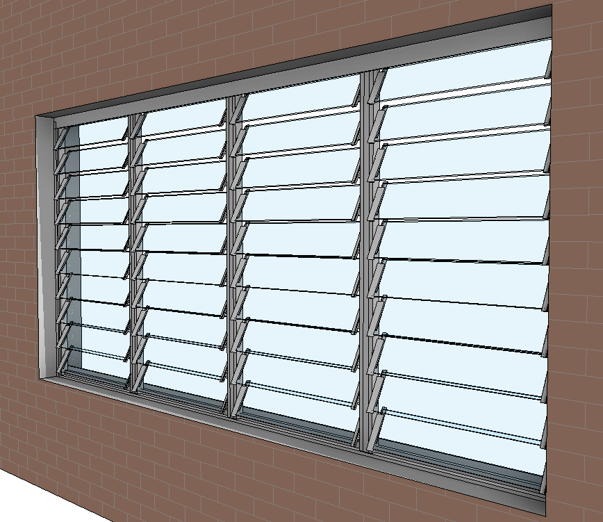
A few months ago Xrev was tasked with creating a series of louvre windows for one of our clients. We don’t like to do things by halves so we set out to create the best louvre window available.
Before we started we established the requirements:
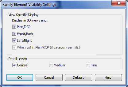
- Appropriate detail display at Coarse, Medium & Fine to avoid excessive linework in plans/elevations & section.
- The ability for the user to specify any number of bays including 1, from within the same family.
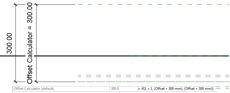
- The ability to control the position of the window within the wall (offset in both directions)
- The ability to control whether the openness of the louvres
- The ability to specify whether the louvres are Glass, Aluminium or Timber
- The ability to have non-standard heights and correctly display the infill panel
- The ability to change the louvre blade size between 152mm and 102mm
- An acceptable file size and performance when making changes
- Report to the user when they have selected a non-standard height that is not available from the manufacturer. EG: Exceeding the maximum height, width, bay width, or setting to an off-standard height that isn’t supported (there are “dead zones” for custom heights).
- Control visibility of Weather Seals
- Control the Frame Material
- Display Structural mullions when the Height exceeds a particular threshold
Did we achieve all of these? Absolutely. Lets look at how we addressed each of these items.
- We simply provided different geometry for coarse that uses a surface pattern for the louvre display. At medium we we turned off the clips and turn off the coarse display, at fine we show the clips.
- This one was trickier. Of course we made use of nesting families. We modelled up a single louvre blade, nested that into a single louvre bay where they were arrayed and nested that into the host family. This actually keeps the file size down and gives us a much more control so we can add parameters. In the host family we had an array for multiple bays, and then a separate “single” element for when the user just selects one bay. We then simply tell the “array” to be off if the user sets it to 1. “Multi” = not(Number of Bays < 2). We then control the array so the family can’t break by adding the following formula. “Actual Bays” = if(Number of Bays < 2, 2, Number of Bays). Essentially we have two sets of parameters, ones that the user inputs what they “want” and another set that actually drive the geometry where we do some validation to ensure that we give them what they want, but only if its possible. Of course it gets trickier again as we also have the mullions that we need to control, but I won’t get into that.
- As you may know, a parameter that is driven by a dimension cannot flip directions to be a negative value. As such we again have to use a little workaround to achieve this. PLEASE NOTE: The rule is a simply “Offset + 300” I’ve just added the conditional statement so the parameter value cannot be edited by the end user.
- In the Louvre Blade family, I have created all the geometry so it is hosted on a reference line that I have a parameter attached to allow me to change the angle. Always use reference “lines” to control angles. These parameters are then “linked” through the various levels of nesting.
- Louvre material is just simply a material parameter, not tricks there.
- Having the infill panels work was quite difficult. To limit file size I didn’t want to create a new family just for those. As such I added a parametric void the louvre blade family. I created a switch using an On/Off parameter called Extension Infill, that drives a parameter the moves the void up and down so it intercepts the blade geometry and cuts it only when necessary. In my Bay family I then had this Infill panel as a new “type”, Tied it to a visibility parameter so its only visible when the overall height requires an infill. The formulas to determine the infill size get quite long. “Infill Size” = if((Height – Bottom Spacing – Top Spacing – ((Number Blades – 1) * Spacing)) < 1 mm, 100 mm, (Height – Bottom Spacing – Top Spacing – ((Number Blades – 1) * Spacing) + 26.4 mm))
- Changing the blade size was just a parameter I built into the extrusion in the louvre blade family. Getting the complicated geometry of the clips to constrain and update was a bit more complicated, as I still needed to control the angle so all this needed to be constrained off the Reference Line.
- For each nested family I ensured they were full purged, only included the required geometry, and limited the number of nested families by having more parametric types rather than additional families. Overall file size is 800KB. Considering how many families it would take to achieve the same amount of options which would each be about 550KB at their leanest, I think this is quite acceptable.
- For the error message I embedded a symbol family that displays the text I want to see. This is then connected to a visibility parameter that is driven by a formula that validates whether it needs to display or not. “Error Message” = or(and(Actual Blade Length > 952 mm, Blade 152, not(Timber Blade)), and(Actual Blade Length > 972 mm, Blade 152, Timber Blade), and(Actual Blade Length > 822 mm, Blade 102, Timber Blade), and(Actual Blade Length > 802 mm, Blade 102, not(Timber Blade)), and(Height > 3018 mm, Blade 152), and(Height > 3048 mm, Blade 102))
- The next two items are simply material and visibility parameter options.
- The structural manual is required if the height is greater than 1500mm. A pretty simple formula.
Anyway, I hope that gives some insight into the lengths we go to to ensure our clients get the best content available and that we always have the end user in mind. We always populate all the identitiy data parameters, omniclass & uniformat, conform to ANZRS and ultimately make the content robust and easy to use as well as ensuring that it displays appropriately in your documentation.


Pingback: Plan ahead when making a family | BIM i praksis